F1-17 Elevator Safety Brake System
Safety Component
F1-17-BRAKE F1-17 Elevator Safety Brake System
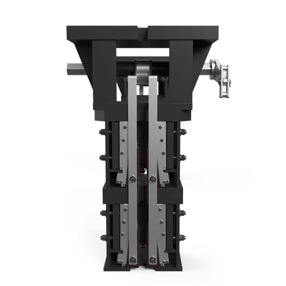
F1-17 Elevator Safety Brake System
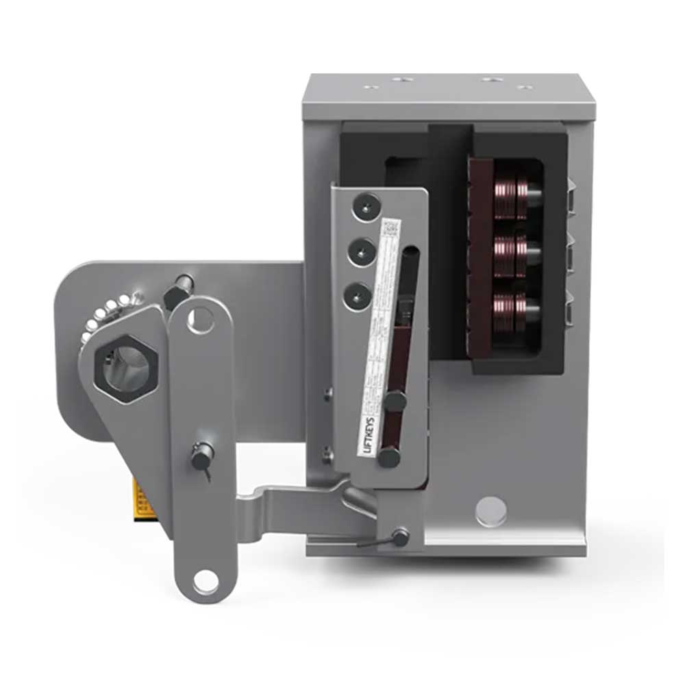
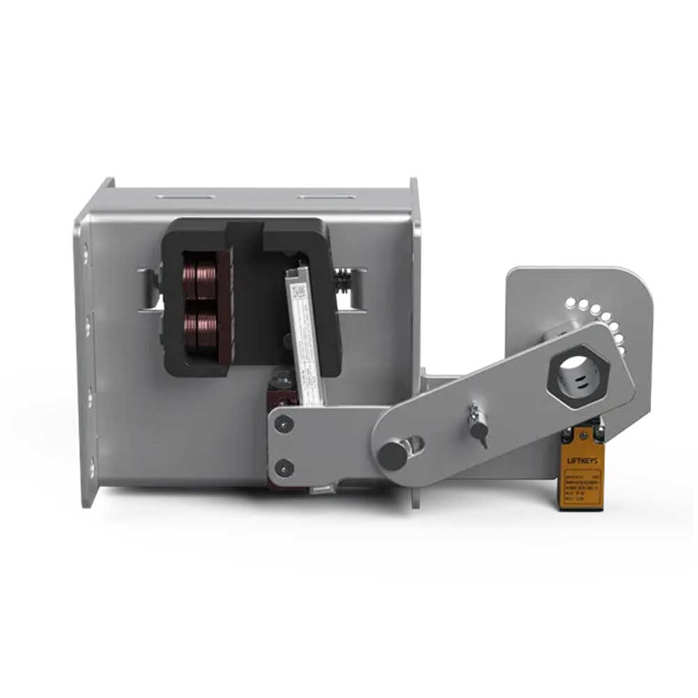
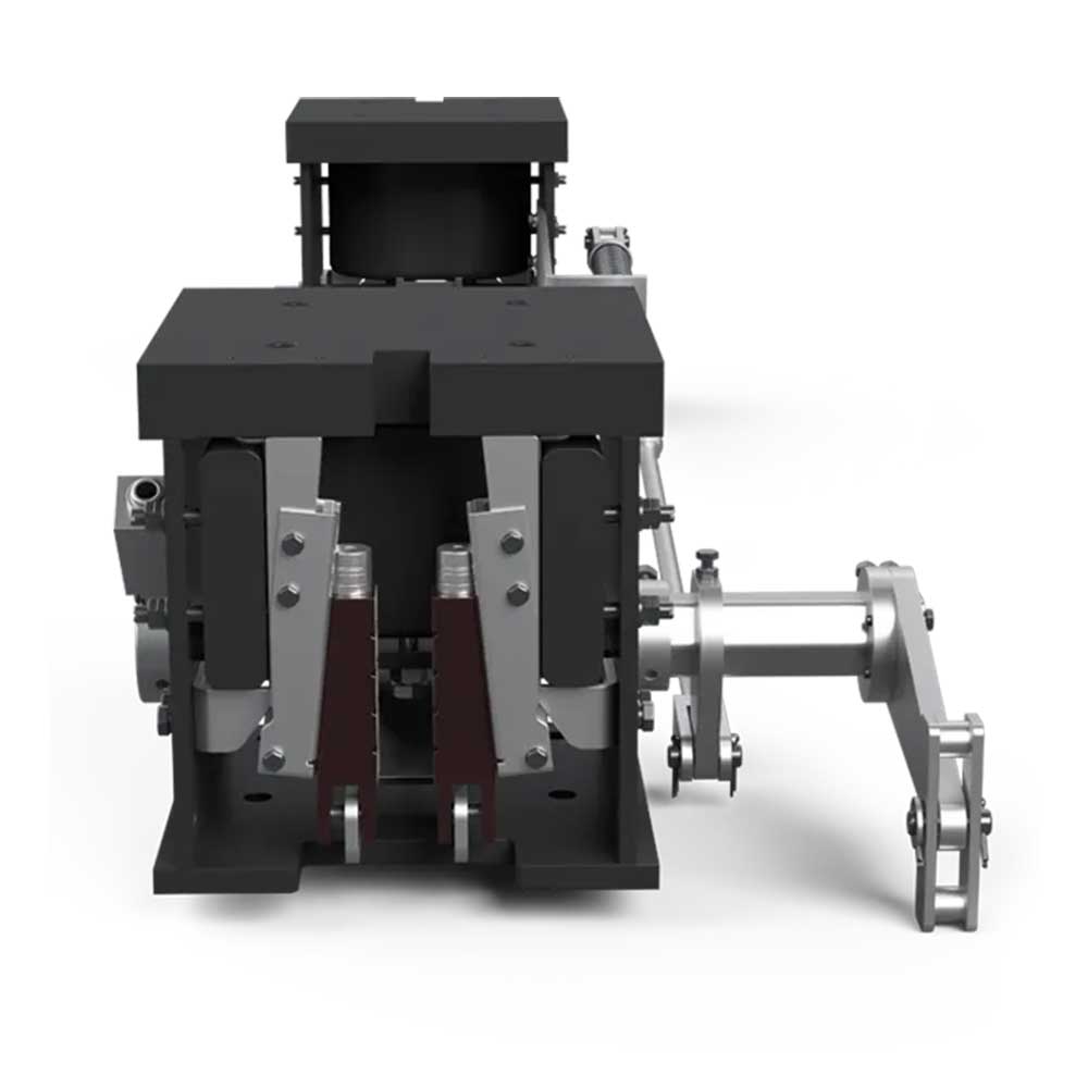
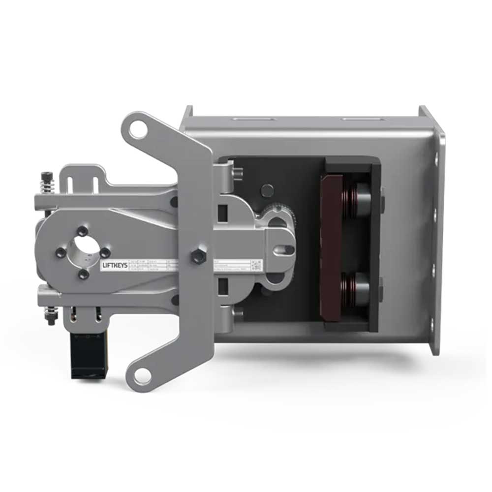
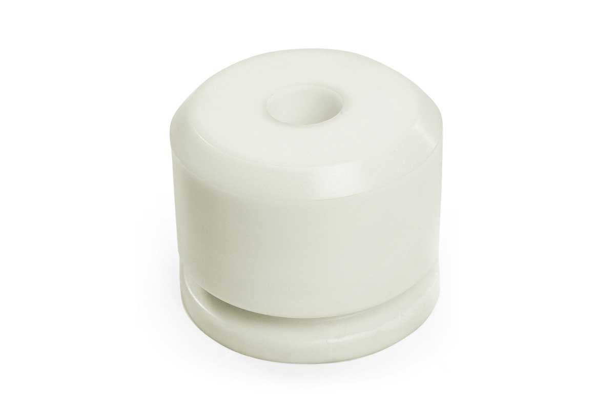
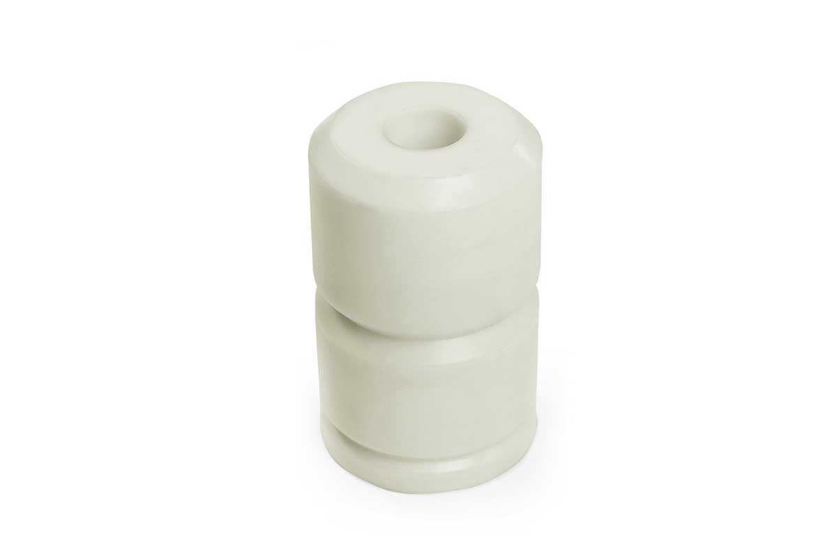
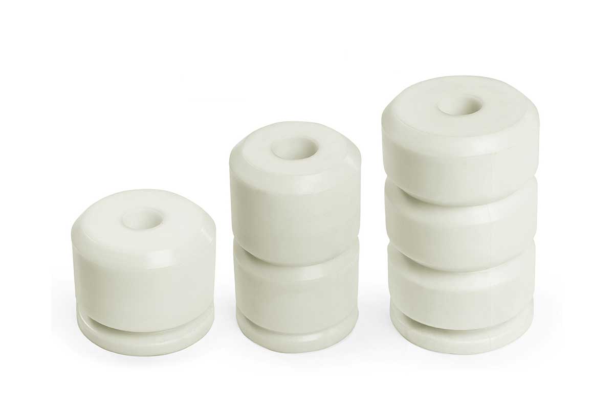
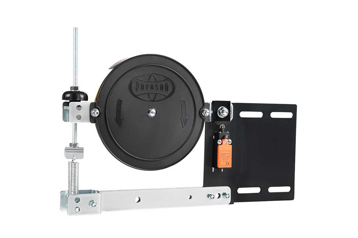
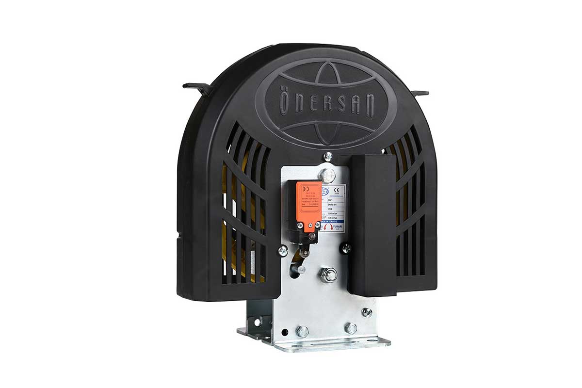
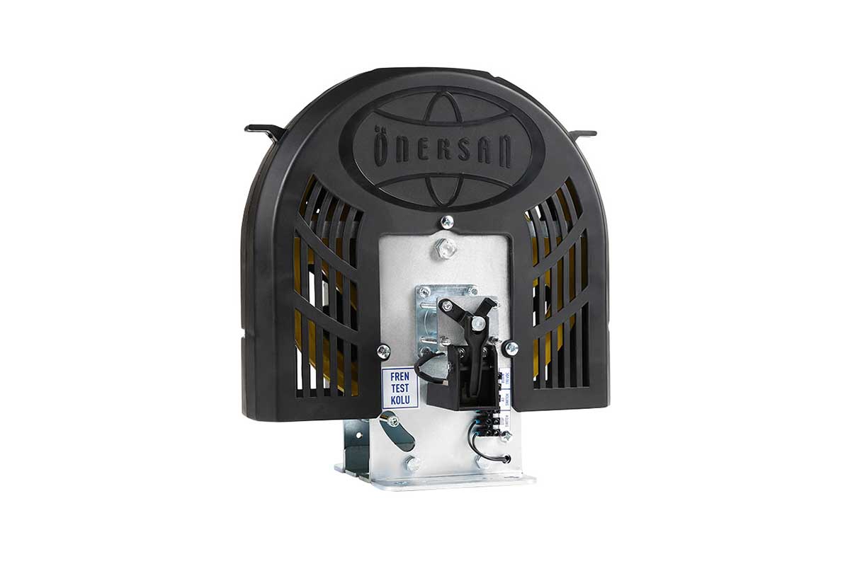
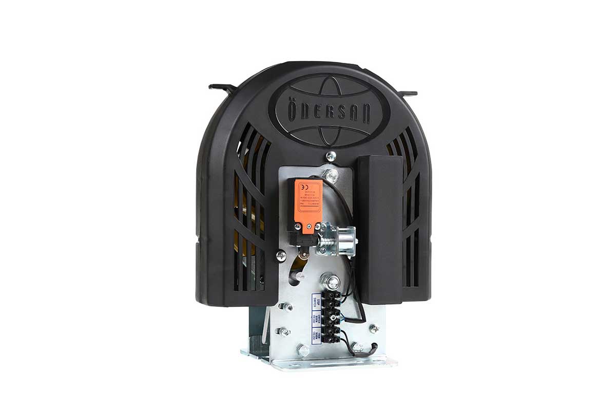
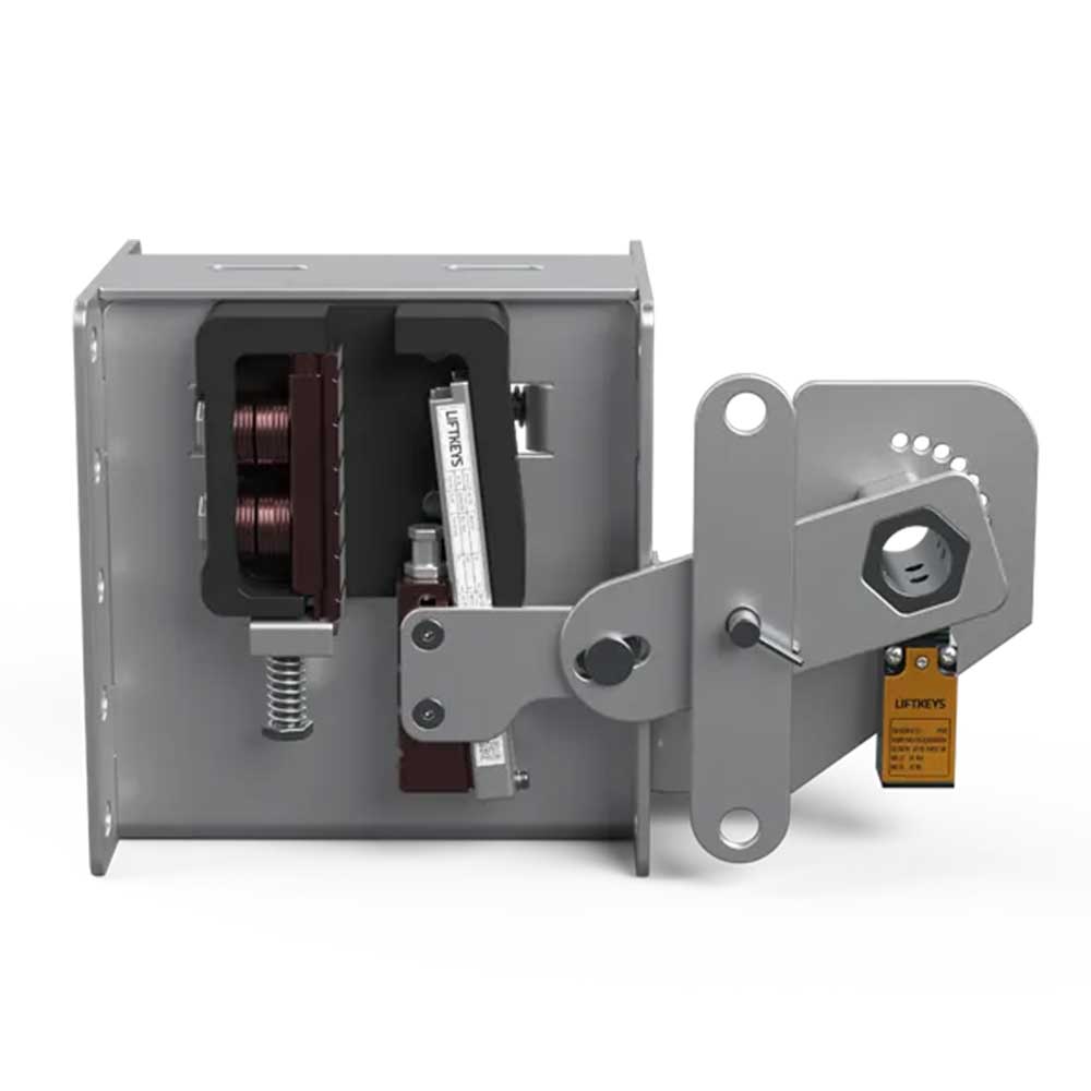
F1-17 Elevator Safety Brake System should be considered as part of the mechanical braking and safety-gear family used in elevator modernization and safety-component renewal projects. The objective is not merely to fit a new part where an old unit was removed; the relationship between car movement, guide rails, mechanical triggering arrangement and the overall elevator safety chain must remain technically coherent. For the F1-17 variant, mounting geometry, linkage or triggering arrangement, movement clearances and direction of mechanical travel should be checked as one complete system. Visual similarity alone must never be treated as proof that two safety brake units are interchangeable.
Before dismantling the existing assembly, the original mounting points, guide-rail arrangement, fixing surfaces on the car frame or supporting structure, orientation of mechanical links and available movement space should be documented. Dimensional fit is important, but it is only one part of compatibility. The mounting plate, fasteners, actuating linkage, moving elements and surfaces that work in relation to the guide rail must be evaluated together. A component that looks similar may still use different fixing dimensions, linkage travel or operating geometry, so replacement should be based on verified project data rather than appearance.
Modernization, Compatibility and Installation
When selecting F1-17 Elevator Safety Brake System, the elevator type, car and frame construction, guide-rail system, mechanism that activates the safety device, connection points and service access should be assessed together. During modernization, mounting-hole positions, body orientation, linkage travel and possible interference with neighboring components must be checked carefully. Moving parts should operate without binding, should not contact cables or unrelated installation elements, and maintenance personnel should retain safe access to inspection and adjustment points after installation.
Commissioning requires more than confirming that the unit is physically installed. Fastener condition, freedom of joints and moving parts, correct direction of the triggering mechanism, mechanical return behavior and the expected response of the associated safety arrangement should be verified in accordance with authorized technical procedures. Functional tests for braking or safety gear must follow the current documentation and commissioning/maintenance procedures applicable to the elevator system. Exact operating force, rail dimensions, speed range, rated capacity or certification must not be inferred from product photographs.
Maintenance, Inspection and Project Verification
Periodic maintenance should include inspection of the body and mounting points, signs of loosening or deformation, freedom of articulated and moving elements, condition of fasteners, rail-related working surfaces and movement of the triggering mechanism. Dirt, corrosion, wear, misalignment or mechanical binding may affect the expected operation of a safety component. If one part appears worn, connected elements should also be inspected so that the underlying cause is understood before parts are replaced without diagnosis.
Project approval for F1-17 Elevator Safety Brake System should be based on the product code, physical arrangement, existing mounting geometry and the complete safety architecture of the elevator. Variants within the same family may look similar while using different connection details or application requirements. Critical information such as exact dimensions, compatible rail characteristics, operating parameters, capacity, certification and standards compliance should therefore be confirmed from current technical documentation for the supplied revision. This approach supports accurate selection, reliable modernization and maintainable elevator safety brake installations.