Elevator Roller Limit Switch 05
Electrical Component
LIMIT-ROLLER-05 Elevator Roller Limit Switch 05
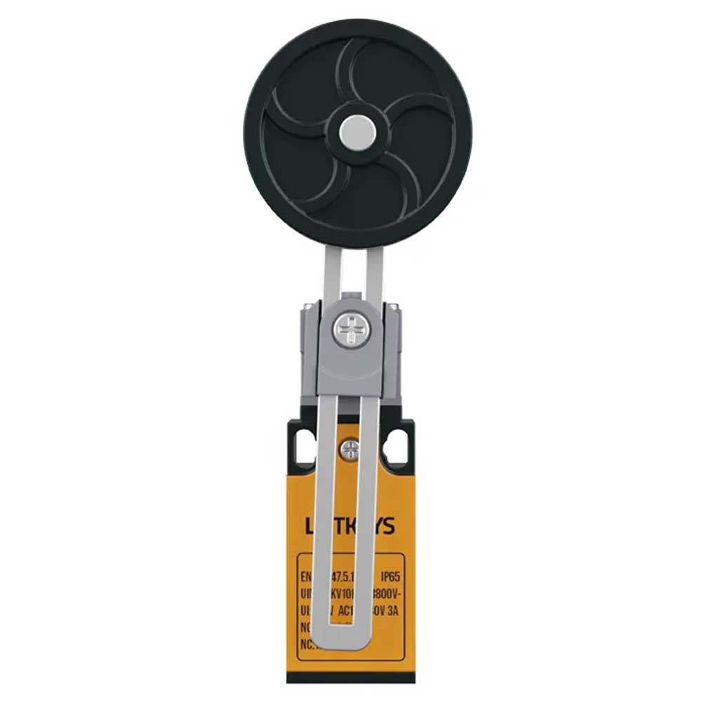
Elevator Roller Limit Switch 05
Elevator Roller Limit Switch 05 is a limit switch using a large roller lever to detect mechanical contact and send position or travel-limit information to the control circuit. In elevator modernization, a limit switch is not merely an on/off device; it is the interface that converts a mechanical position into an electrical state used by the control system. Selection should therefore consider actuator type, approach direction, movement geometry, mounting position, terminal arrangement and the operating logic of the existing controller together. Products with similar enclosures may use different actuators, reset behavior or contact arrangements, so appearance alone is not enough for interchangeability.
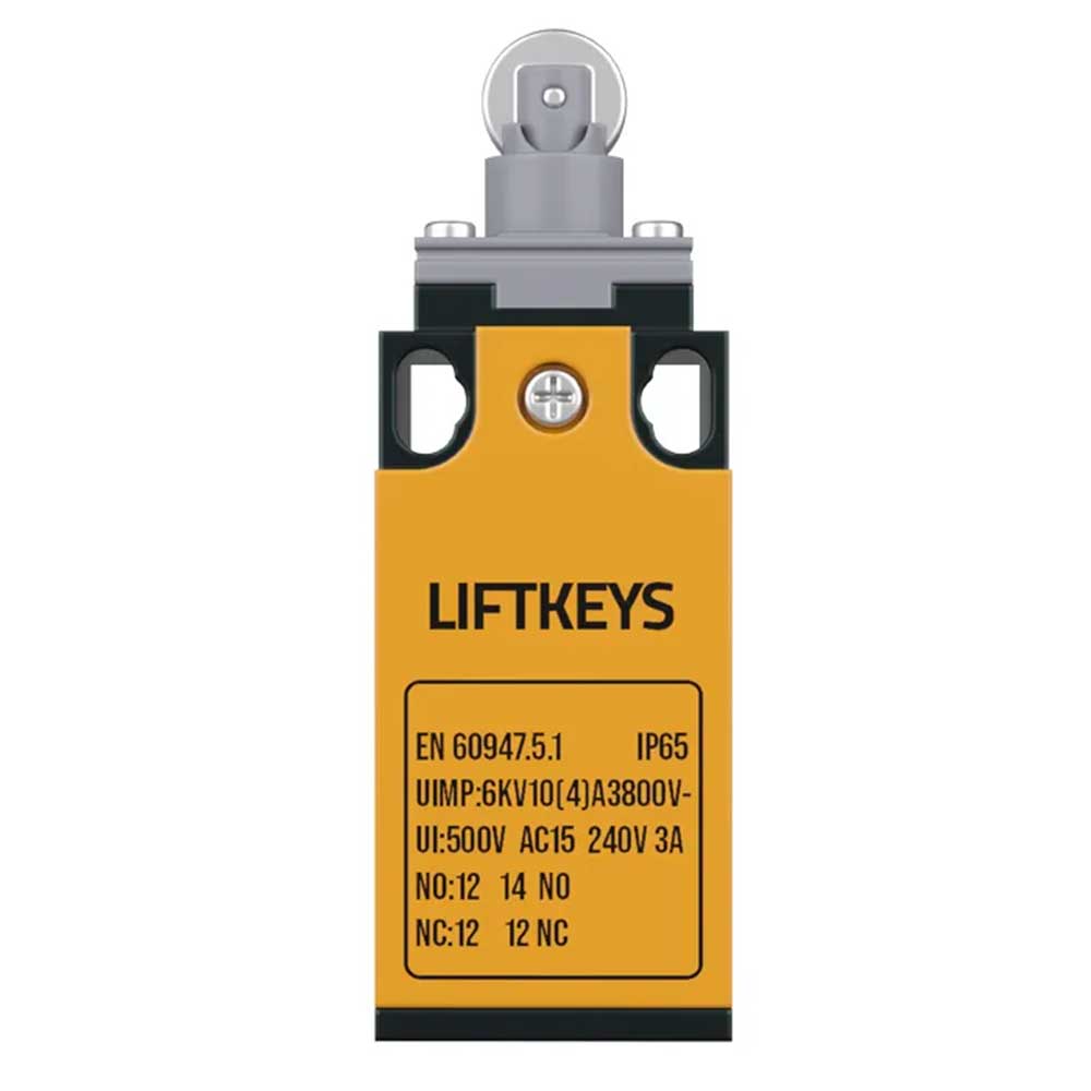
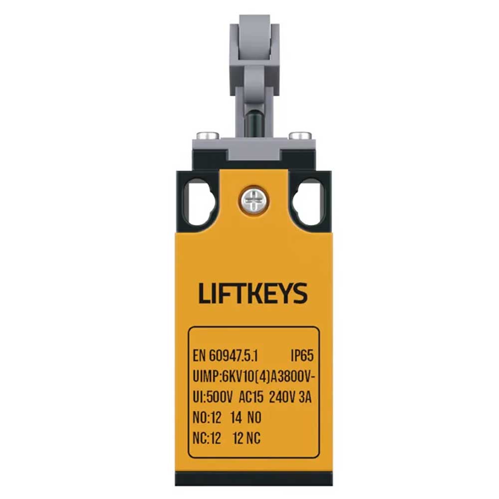
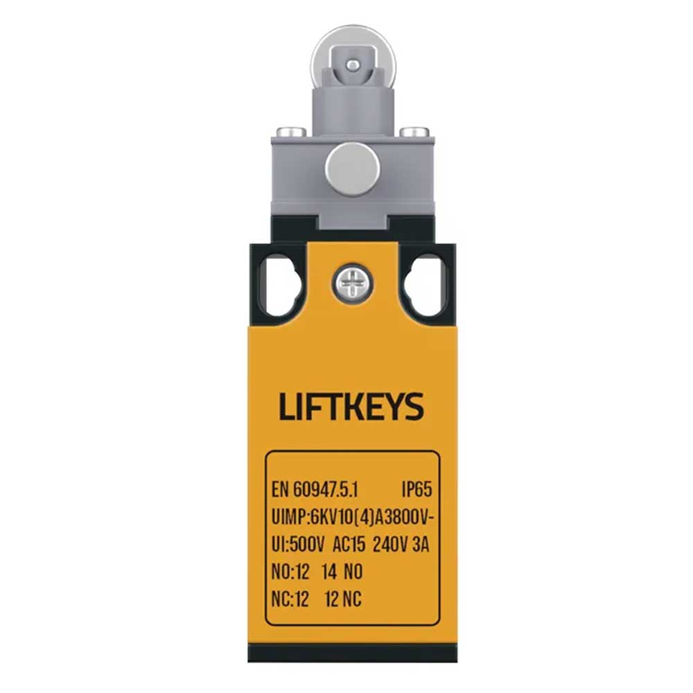
For this product, specifically verify large-roller contact path, lever angle, approach direction, actuation distance, mounting slots, terminal wiring, NO/NC use and clearance to nearby moving parts. The product label visible in the supplied images shows EN 60947-5-1, IP65, Uimp 6 kV, Ui 500 V and AC-15 240 V / 3 A, and NO and NC contact references are also visible. These markings support identification, but actual field wiring should never be inferred only from the photograph. Terminal markings, cable ends, the installed circuit diagram and controller input logic should be checked together.
Installation, Electrical Compatibility and Commissioning
Before installation, record which mechanical element actuates the existing switch, from which direction and at what point in the movement. Mount the replacement body without distorting the mounting surface and position the actuator so that contact with the moving mechanism is controlled. Roller and lever actuators should not receive excessive side load, overtravel or an unsuitable approach angle. Mounting slots should be used for correct switching-point adjustment rather than forcing the product to match an incorrect mechanical geometry.
Before electrical connection, isolate the supply safely and verify absence of voltage. Decide whether NO or NC terminals are used according to the existing elevator control function. Inspect old cable ends for oxidation, looseness, insulation damage, unsuitable splices and incorrect identification. Cable routing should be protected from moving parts, sharp edges and pinch points, and the cable entry should be arranged so the intended enclosure protection is not compromised.
Maintenance, Testing and Project Verification
During commissioning, actuate the switch repeatedly in a controlled manner and observe free actuator movement. For variants identified in the source name as reset or non-reset, confirm that the mechanical behavior is consistent with that description. Do not accept an audible click alone as proof of correct switching; verify NO/NC state change by measurement, controller input indication or another appropriate test. The actual switching point should occur with suitable margin before the moving mechanism reaches an unsafe physical limit.
Periodic maintenance should inspect the enclosure, mounting screws, actuator, roller or lever, cable entry and terminals for looseness, contamination, wear, bending, cracking and mechanical damage. A forced actuator, seized roller, altered lever geometry or shifted mounting position can move the switching point. If a fault appears, inspect the mechanical part that actuates the switch, the cable path and the relevant controller input rather than replacing only the switch.
The electrical label values visible in the supplied photographs are retained in the product content, but exact terminal numbering, actual contact arrangement, switching life, operating force, mechanical travel, temperature range, cable gland and functional compatibility with a specific elevator model should be confirmed from current documentation. Recording the model, actuator type, mounting position, NO/NC function used and commissioning result reduces confusion during future maintenance and spare-part selection. This approach supports reliable position detection, correct electrical integration and easier servicing of Elevator Roller Limit Switch 05.