Adjustable Elevator Buffer Stand
Buffer Mounting Plates
MZ28-TAMPON-AYAR Adjustable Elevator Buffer Stand
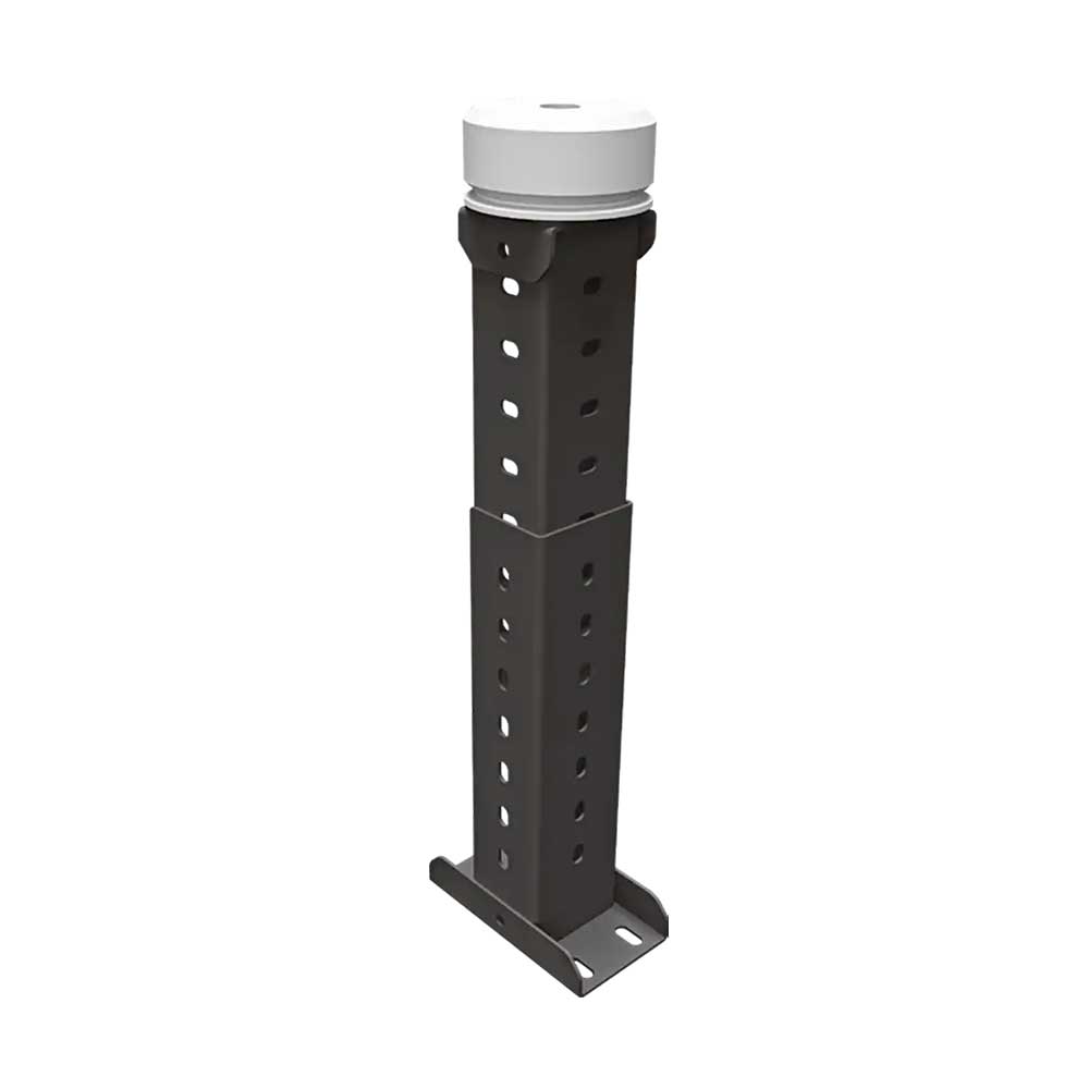
Adjustable Elevator Buffer Stand
The adjustable elevator buffer stand coordinates pit buffer positioning with its supporting connections. For selection, existing mounting dimensions and the corresponding mounting connections are assessed together against the current technical project drawings.
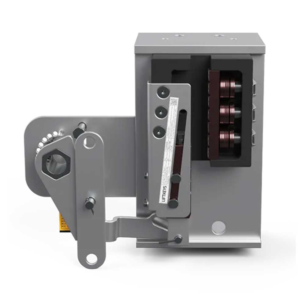
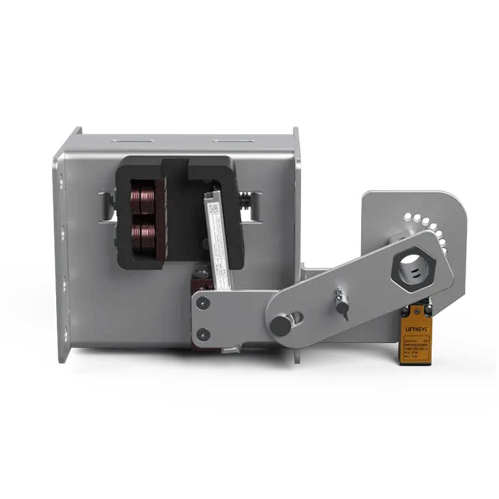
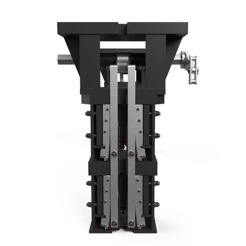
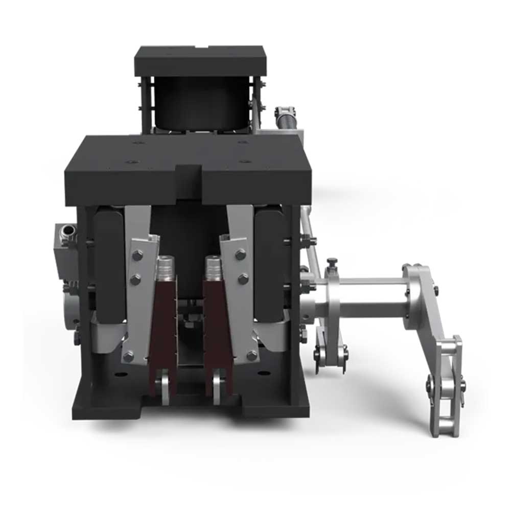
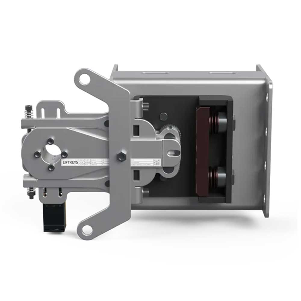
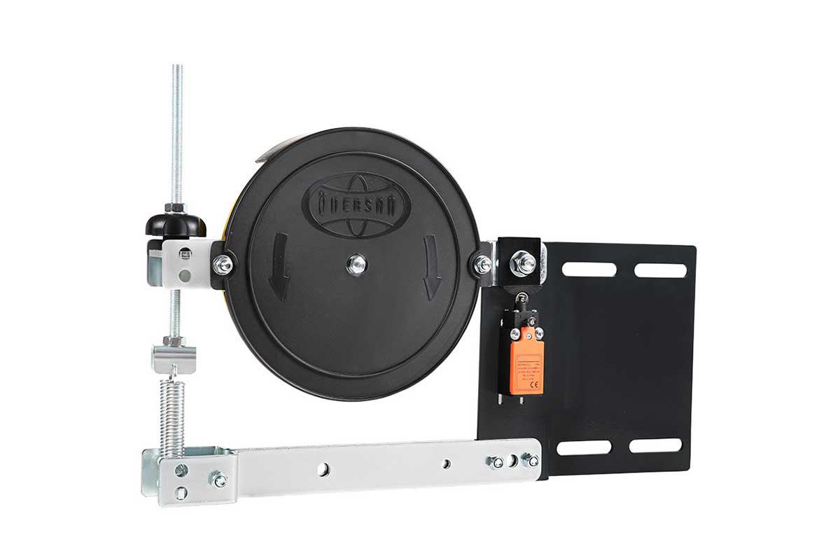
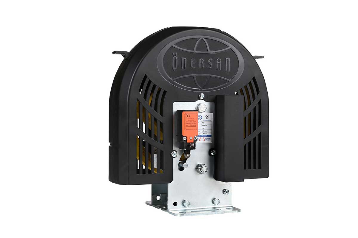
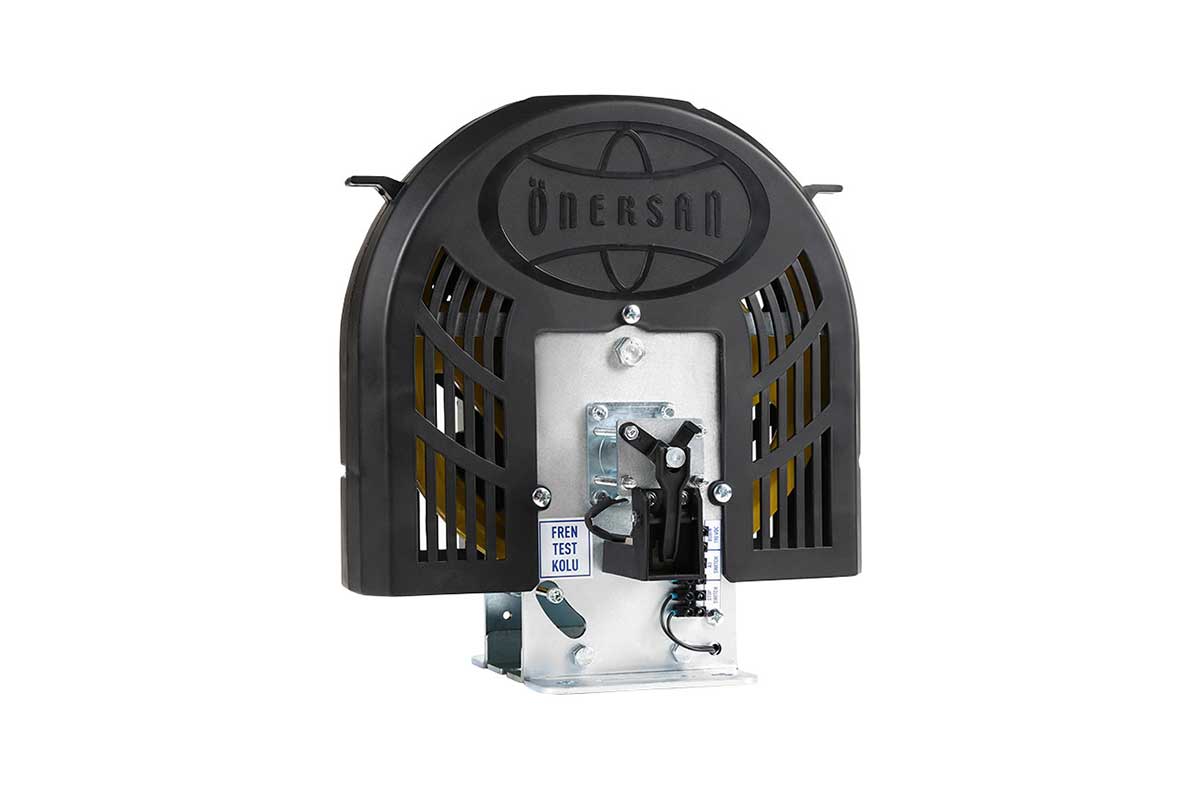
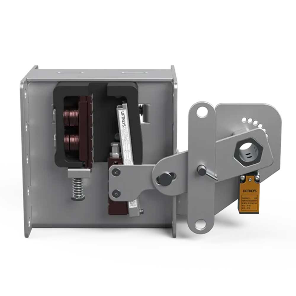
The image shows an adjustable stand with a perforated upright, base fixings and an upper buffer seating area. The hole pattern and required installation height are compared with the technical drawing for the selected product.
Application and Product Selection
A buffer stand combines the positioning of the pit buffer with its supporting connections. Modernisation considers the existing pit depth, car and counterweight stopping geometry, buffer type and floor fixings together. Selection compares the installation dimensions with the project layout so that equipment positions and the specified clearances can be assessed as one arrangement.
Before ordering, establish the buffer seating dimensions, base fixing positions and required mounting height. The adjustment feature does not replace the project's clearance assessment. Floor suitability, fasteners and load transfer are considered with the application drawings and the requirements of the complete buffer installation.
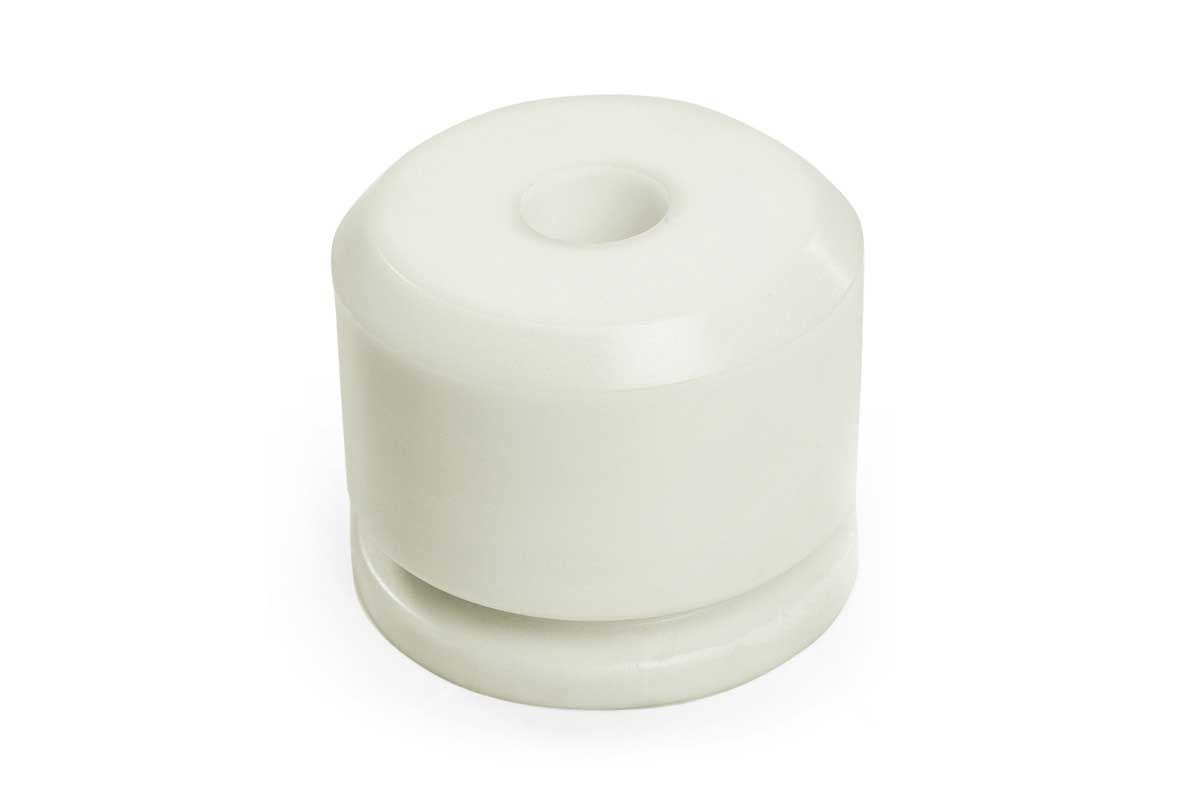
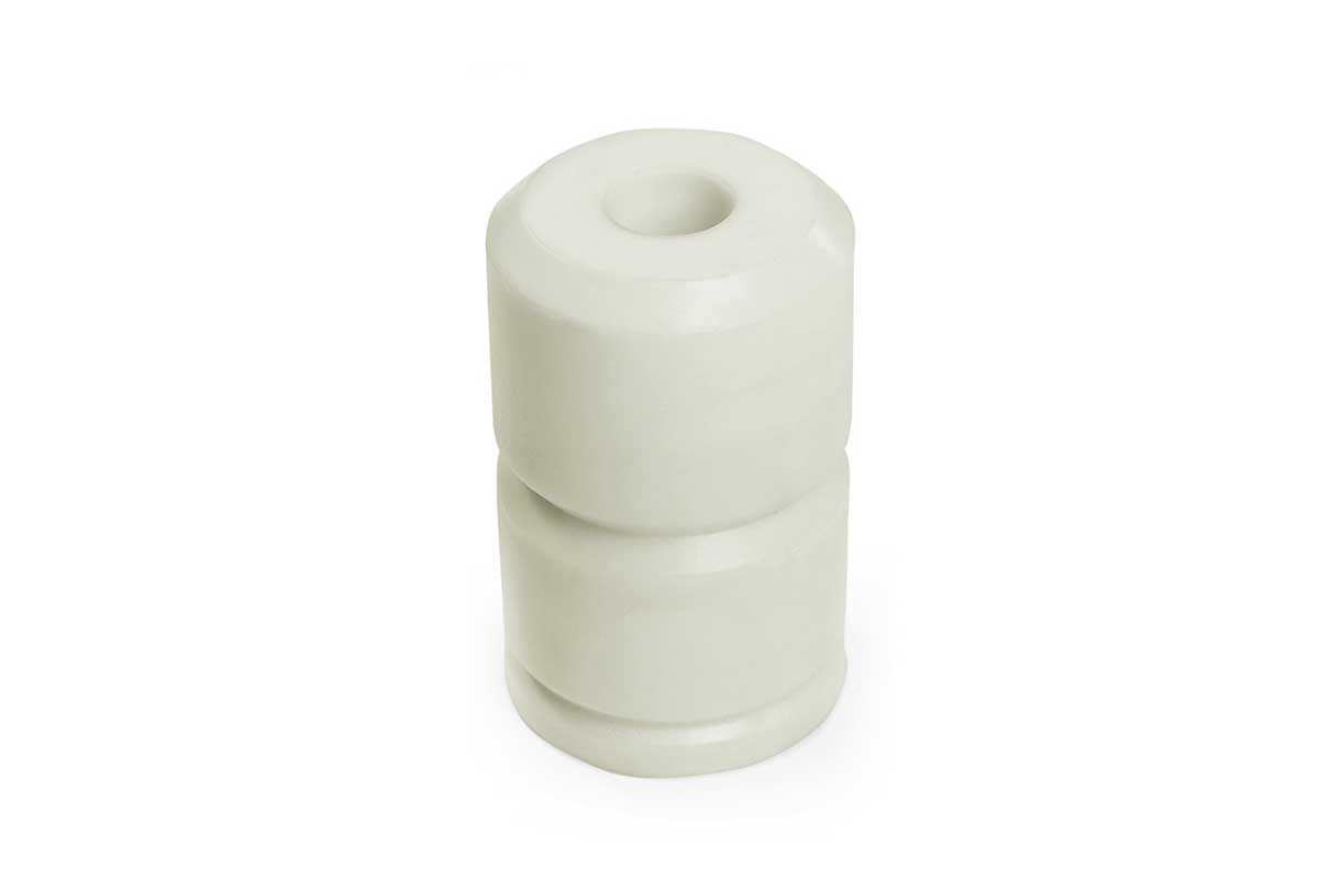
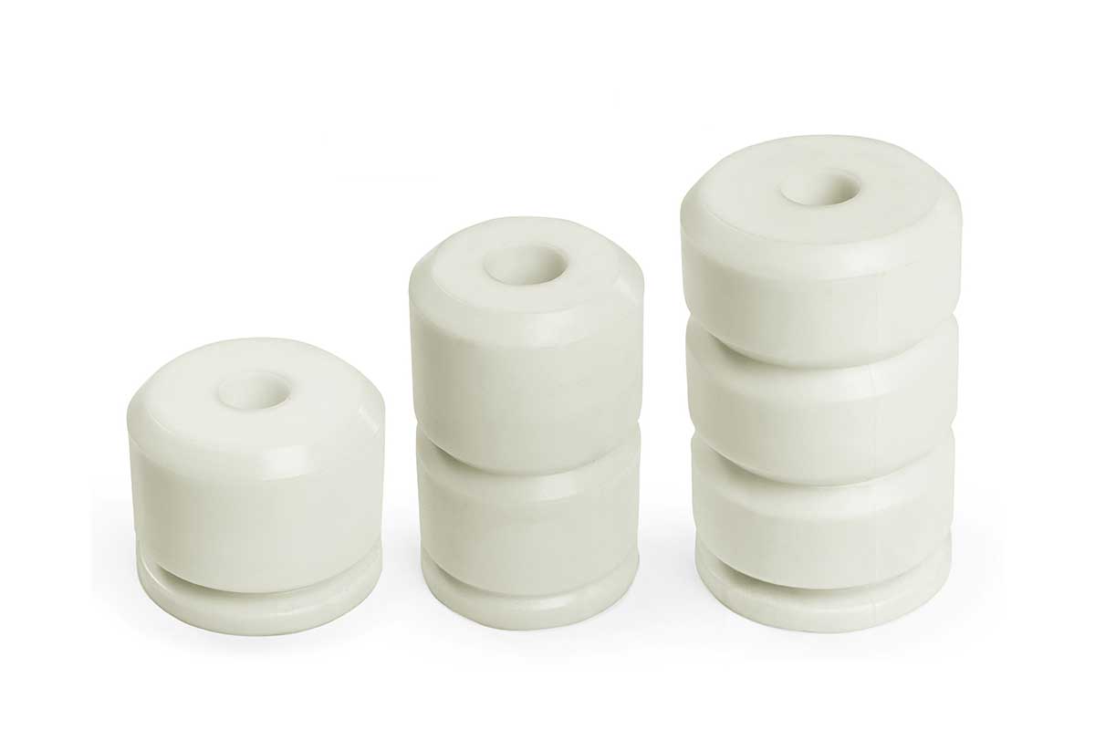
A product should not be selected solely from a photograph or a similar model name. Exact dimensions, connection arrangements, operating conditions and system compatibility should be assessed against current technical documentation. Images show the general product form and do not replace a scaled manufacturing drawing.
Installation Planning and Maintenance
Before replacement, record the position of the existing component, its fixing points, interacting parts and maintenance access. Installation planning should cover dimensional comparison, suitable fasteners and the way components operate together. Installation and commissioning checks should be carried out by qualified personnel in accordance with the product instructions and the technical requirements of the project.
Periodic inspection covers the body, base fixings, joints and buffer seating surface. Bending, corrosion, loosening or changes in position are recorded. Any adjustment or moving connections are examined according to the product instructions. The buffer and stand are considered together, with maintenance access and the documented installation layout included in the inspection plan.
Keep the product code, selected variant, quantity, installation position and technical documents in the project file for maintenance and future sourcing. Reference photographs and dimensional records of the replaced component can also be included. This provides a traceable basis for selecting components for subsequent modernization work on other elevators with the same arrangement. For traceable product selection, record the measurement date, installation position, component name and revision of the technical drawing used to compare the existing assembly with the selected configuration.
Modernization Project and Quotation
When requesting a product assessment or quotation from Katrelift, share the model code, required quantity, a photograph of the existing component and the relevant fixing dimensions. Indicating whether the project concerns a new installation, maintenance or modernization helps identify the appropriate variant and the associated components that should be considered together.