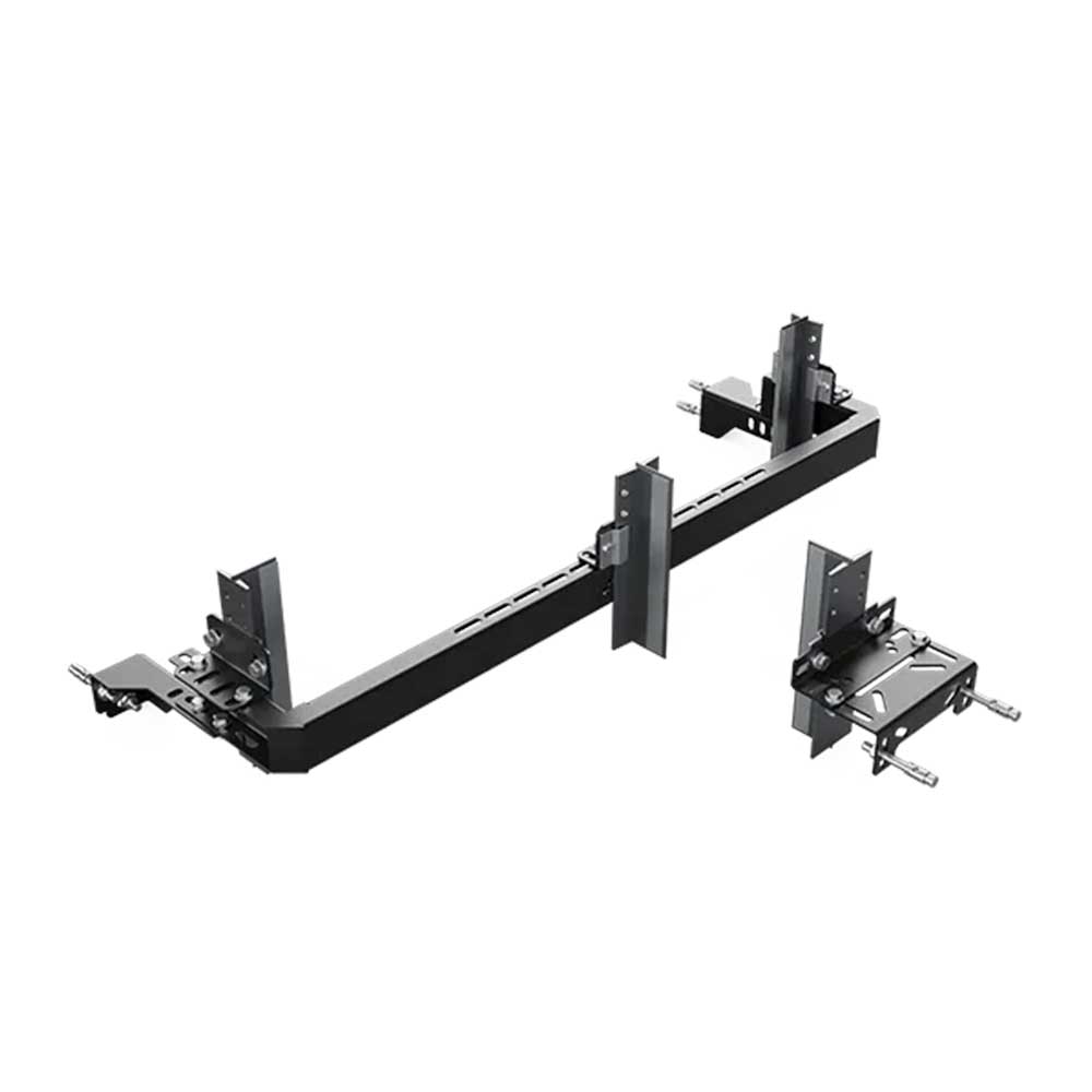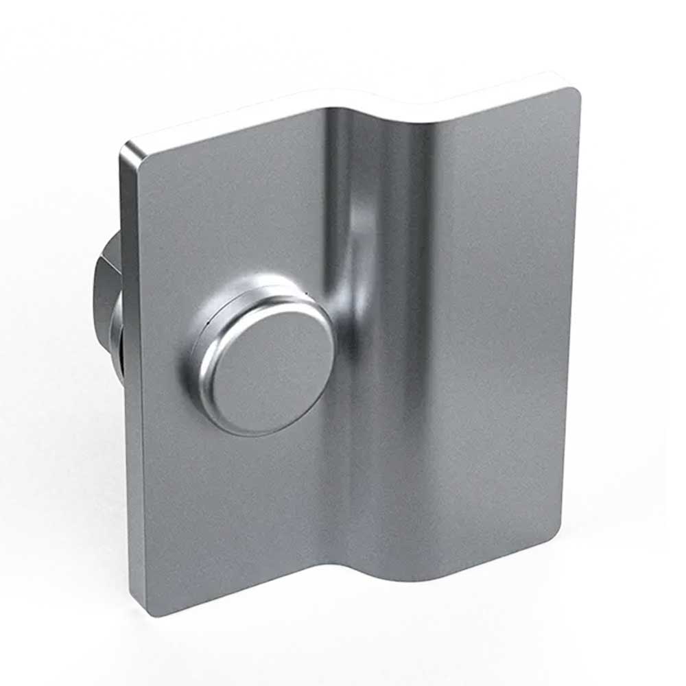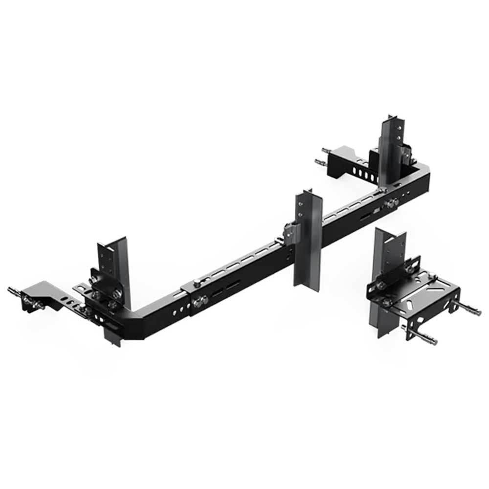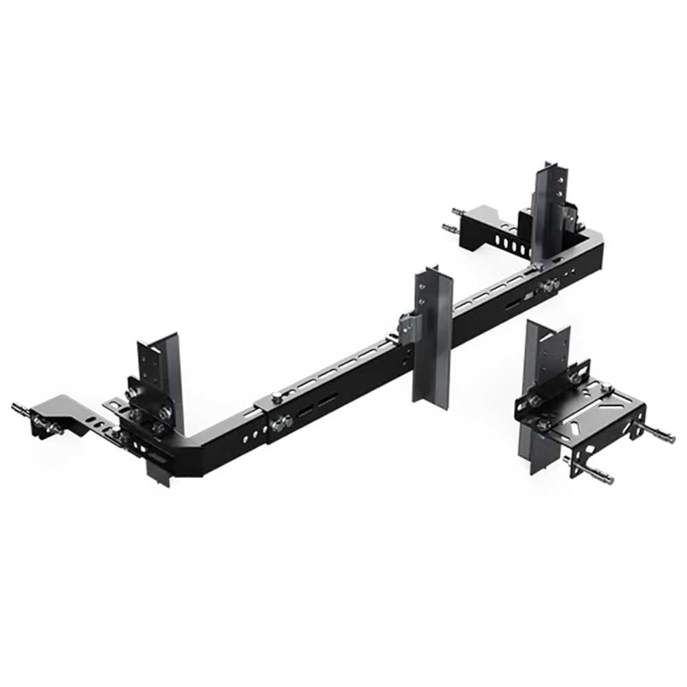
Mega Side Counterweight Bracket – Rail Spacing 970-1650 – T45-145 – Ç320-540
Shaft Component
MEGA-YAN-AGIRLIK-970-1650-T45-145-C320-540 Mega Side Counterweight Bracket – Rail Spacing 970-1650 – T45-145 – Ç320-540
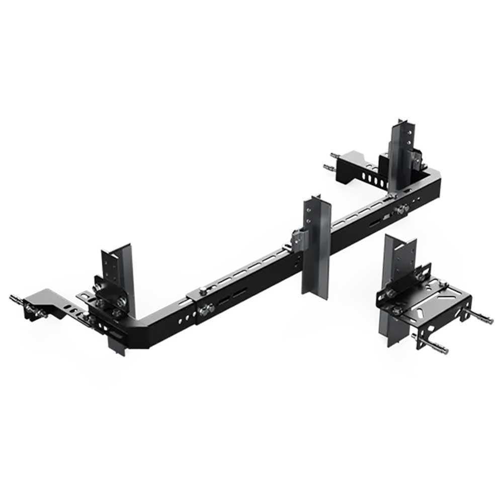
Mega Side Counterweight Bracket – Rail Spacing 970-1650 – T45-145 – Ç320-540
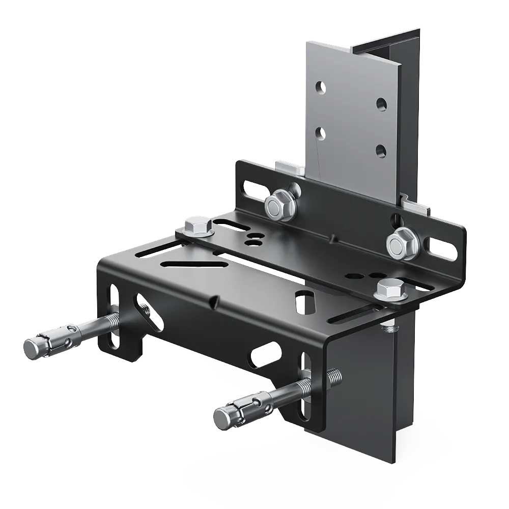
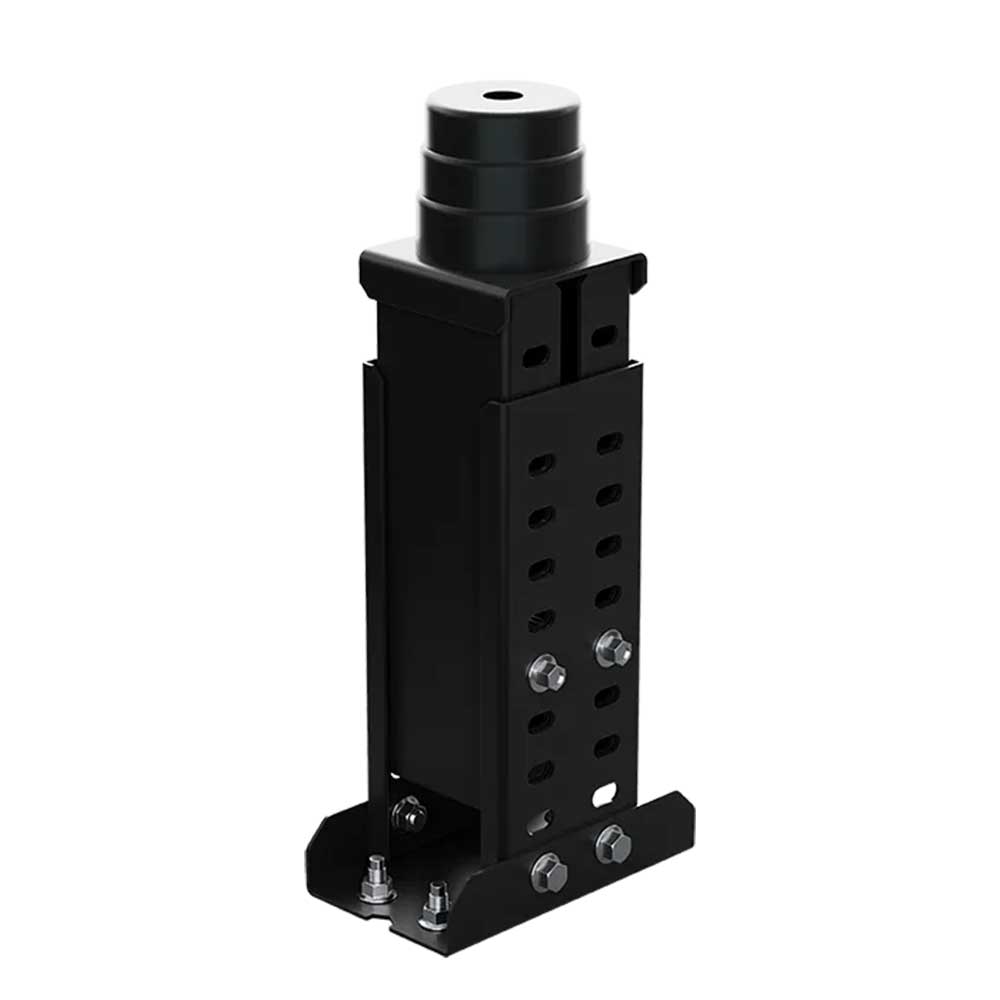
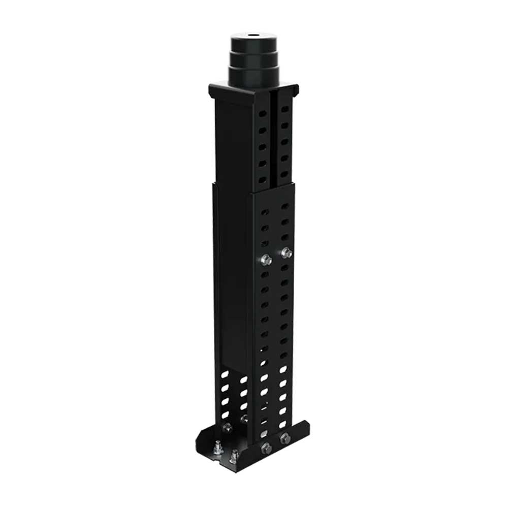
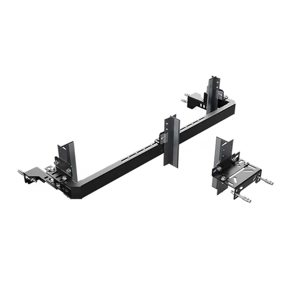
Mega Side Counterweight Bracket – Rail Spacing 970-1650 – T45-145 – Ç320-540 is an adjustable or fixed bracket system used to position counterweight guide rails and related shaft mounting elements from the side. In shaft and guide-rail installation work, physical fit alone is not enough; rail axes, counterweight or buffer position, shaft wall or support surface, mounting plane and fixing hardware must be considered together. Dimensions and variant codes in the product name are retained as part of the product definition, but their exact project meaning and suitability should be verified using site measurements and current technical documentation.
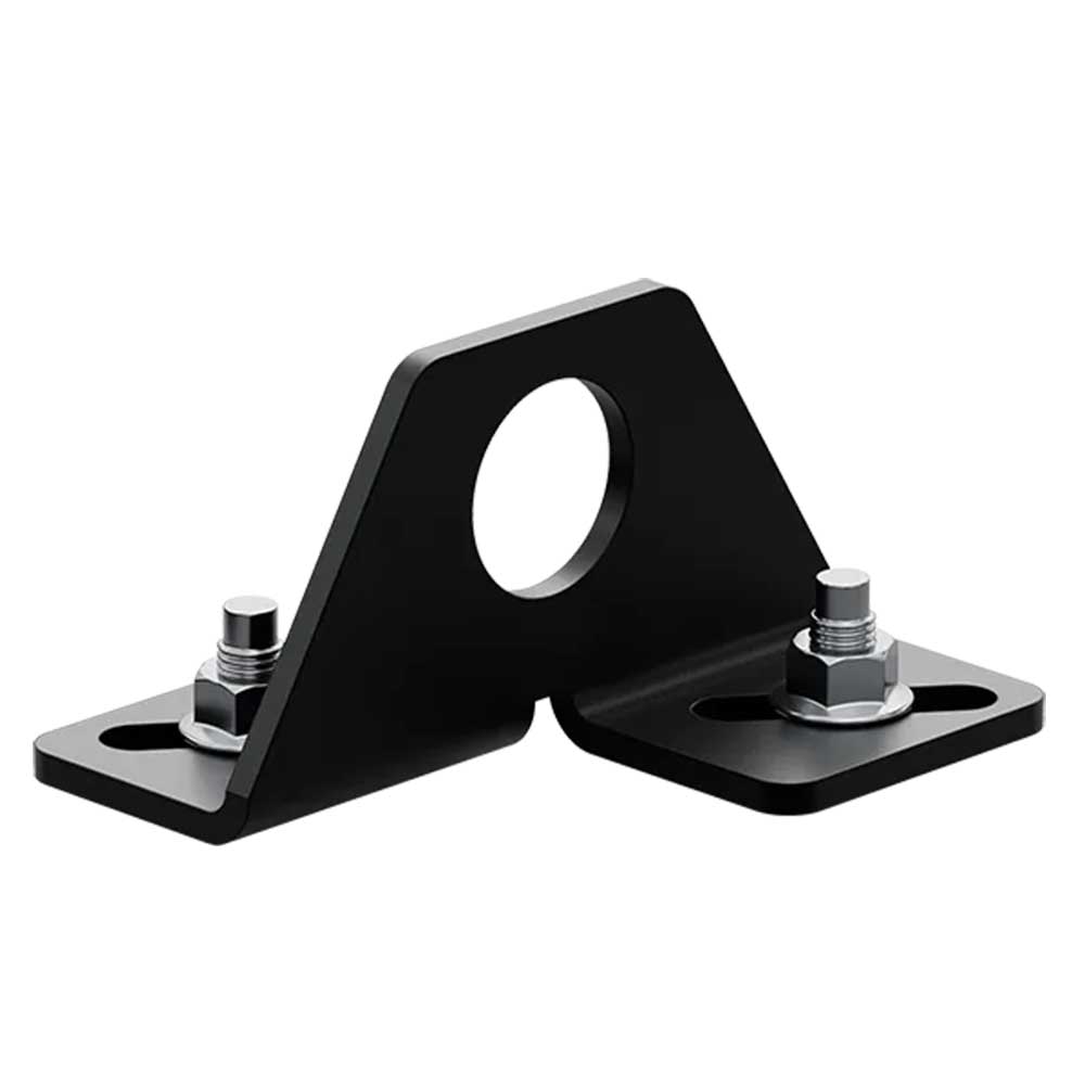
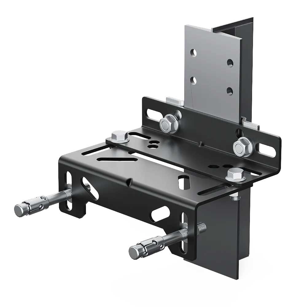
Selection should specifically verify rail-spacing, T, Ç and where applicable G/K designations; bracket span, guide-rail axis, wall or support surface, anchor arrangement, deflection and mechanical alignment. Brackets, clips, buffers and mounting parts that look similar may use different hole patterns, spans, rail compatibility, fixing geometry or revisions. Interchangeability should therefore never be decided from photographs alone. Before dismantling, record the existing part position, guide-rail profile, bolt and anchor arrangement and surrounding mechanical layout for comparison with the replacement.
Modernization, Installation and Geometric Compatibility
Before installation, inspect the integrity of the shaft support surface, the plane under the bracket or base plate, the condition of existing anchors, guide-rail verticality and the relationship between reference axes. Mega Side Counterweight Bracket – Rail Spacing 970-1650 – T45-145 – Ç320-540 should not be forced into position or modified improperly simply to make fixing holes align. Bolts and fixing hardware should be selected according to project and manufacturer requirements.
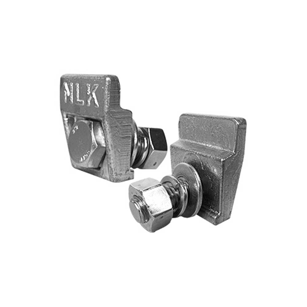
For rail-related installations, review rail-line verticality, joints, bracket spacing and the way clips seat on the rail as one complete geometry. For counterweight brackets, maintain operating clearances between the moving mass and shaft components. For pit-buffer assemblies, verify the contact axis, base fixing and the geometry by which the related moving element meets the buffer.
Commissioning, Maintenance and Project Verification
During commissioning, observe the relevant operating scenario for looseness, deflection, unintended contact, misalignment, rubbing or movement at fixing points. Axis errors in bracket and rail connections can contribute to vibration and wear over time. For buffers and mounting feet, verify within project conditions that load and contact occur along the intended geometry.
Periodic maintenance should inspect Mega Side Counterweight Bracket – Rail Spacing 970-1650 – T45-145 – Ç320-540 together with anchors, bolts, rail clips, bracket surfaces and neighboring mechanical parts for looseness, corrosion, deformation, cracking, wear and alignment. If one fixing point shows a problem, review the wider shaft installation geometry and associated rail line instead of replacing only the visible component.
Exact load capacity, sheet thickness, material grade, anchor type, bolt torque, rail loads, certification or compatibility with a specific elevator model must not be inferred from photographs or the product name. These values should be confirmed from current documentation for the supplied revision, project calculations and actual site measurements. Modernization records should also document old and new part codes, selected variant, rail or wall measurements, fixing points and commissioning checks for future traceability.